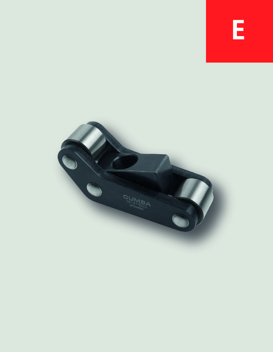
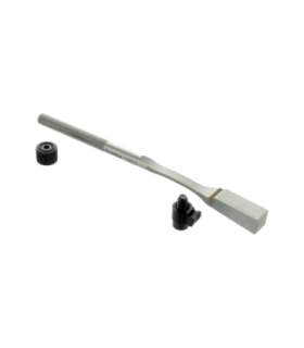
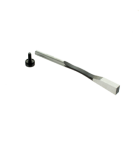
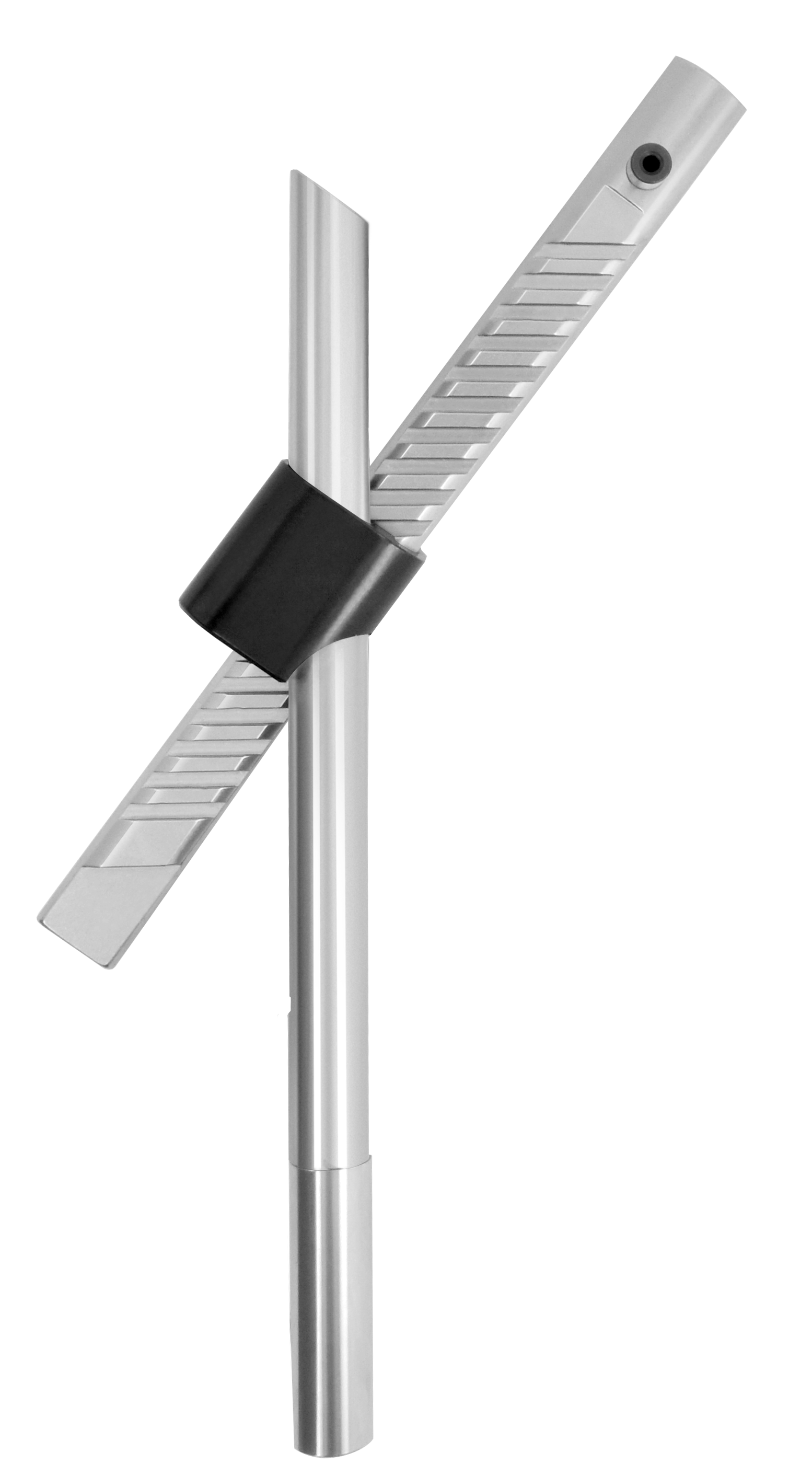
Release small undercuts within 30 or 60mm of ejection stroke.
Allows angles up to 6 degrees.
Customizable insert gives freedom to moldmaker.
Fully mechanical solution.
Easy assembly and installation.
Read moreShow less
Allows angles up to 6 degrees.
Customizable insert gives freedom to moldmaker.
Fully mechanical solution.
Easy assembly and installation.
Which is the stroke obtained with the WORM series (WP/WL)?
Depends on the angle and the ejection stroke, please review this table to have the approximate values:
| Demolding Angles |
| Demolding Strokes | 1º | 2º | 3º | 4º | 5º | 6º |
| 5 mm. (0,197") | 0,09 mm. (0,003") | 0,17 mm. (0,007") | 0,26 mm. (0,01") | 0,35 mm. (0,014") | 0,44 mm. (0,017") | 0,53 mm. (0,021") |
| 10 mm. (0,394") | 0,17 mm. (0,007") | 0,35 mm. (0,014") | 0,52 mm. (0,021") | 0,7 mm. (0,028") | 0,87 mm. (0,034") | 1,05 mm. (0,041") |
| 15 mm. (0,591") | 0,26 mm. (0,01") | 0,52 mm. (0,021") | 0,79 mm. (0,031") | 1,05 mm. (0,041") | 1,31 mm. (0,052") | 1,58 mm. (0,062") |
| 20 mm. (0,787") | 0,35 mm. (0,014") | 0,7 mm. (0,027") | 1,05 mm. (0,041") | 1,4 mm. (0,055") | 1,75 mm. (0,069") | 2,1 mm. (0,083") |
| 25 mm. (0,984") | 0,44 mm. (0,017") | 0,87 mm. (0,034") | 1,31 mm. (0,052") | 1,75 mm. (0,069") | 2,19 mm. (0,086") | 2,63 mm. (0,103") |
| 30 mm. (1,181") | 0,52 mm. (0,021") | 1,05 mm. (0,041") | 1,57 mm. (0,062") | 2,1 mm. (0,083") | 2,62 mm. (0,103") | 3,15 mm. (0,124") |
| 35 mm. (1,378") | 0,61 mm. (0,024") | 1,22 mm. (0,048") | 1,83 mm. (0,072") | 2,45 mm. (0,096") | 3,06 mm. (0,121") | 3,68 mm. (0,145") |
| 40 mm. (1,575") | 0,7 mm. (0,028") | 1,4 mm. (0,055") | 2,1 mm. (0,083") | 2,8 mm. (0,11") | 3,5 mm. (0,138") | 4,2 mm. (0,166") |
| 45 mm. (1,772") | 0,79 mm. (0,031") | 1,57 mm. (0,062") | 2,36 mm. (0,093") | 3,15 mm. (0,124") | 3,94 mm. (0,155") | 4,73 mm. (0,186") |
| 50 mm. (1,969") | 0,87 mm. (0,034") | 1,75 mm. (0,069") | 2,62 mm. (0,103") | 3,5 mm. (0,138") | 4,37 mm. (0,172") | 5,26 mm. (0,207") |
| 55 mm. (2,165") | 0,96 mm. (0,038") | 1,92 mm. (0,076") | 2,88 mm. (0,113") | 3,85 mm. (0,151") | 4,81 mm. (0,189") | 5,78 mm. (0,228") |
| 60 mm. (2,362") | 1,05 mm. (0,041") | 2,1 mm. (0,082") | 3,14 mm. (0,124") | 4,2 mm. (0,165") | 5,25 mm. (0,207") | 6,31 mm. (0,248") |
| 65 mm. (2,559") | 1,13 mm. (0,045") | 2,27 mm. (0,089") | 3,41 mm. (0,134") | 4,55 mm. (0,179") | 5,69 mm. (0,224") | 6,83 mm. (0,269") |
| 70 mm. (2,756") | 1,22 mm. (0,048") | 2,44 mm. (0,096") | 3,67 mm. (0,144") | 4,89 mm. (0,193") | 6,12 mm. (0,241") | 7,36 mm. (0,29") |
| 75 mm. (2,953") | 1,31 mm. (0,052") | 2,62 mm. (0,103") | 3,93 mm. (0,155") | 5,24 mm. (0,206") | 6,56 mm. (0,258") | 7,88 mm. (0,31") |
| 80 mm. (3,15") | 1,4 mm. (0,055") | 2,79 mm. (0,11") | 4,19 mm. (0,165") | 5,59 mm. (0,22") | 7 mm. (0,276") | 8,41 mm. (0,331") |
| 85 mm. (3,346") | 1,48 mm. (0,058") | 2,97 mm. (0,117") | 4,45 mm. (0,175") | 5,94 mm. (0,234") | 7,44 mm. (0,293") | 8,93 mm. (0,352") |
| 90 mm. (3,543") | 1,57 mm. (0,062") | 3,14 mm. (0,124") | 4,72 mm. (0,186") | 6,29 mm. (0,248") | 7,87 mm. (0,31") | 9,46 mm. (0,372") |
| 95 mm. (3,74") | 1,66 mm. (0,065") | 3,32 mm. (0,131") | 4,98 mm. (0,196") | 6,64 mm. (0,262") | 8,31 mm. (0,327") | 9,98 mm. (0,393") |
| 100 mm. (3,937") | 1,75 mm. (0,069") | 3,49 mm. (0,137") | 5,24 mm. (0,206") | 6,99 mm. (0,275") | 8,75 mm. (0,344") | 10,51 mm. (0,414") |
| 105 mm. (4,134") | 1,83 mm. (0,072") | 3,67 mm. (0,144") | 5,5 mm. (0,217") | 7,34 mm. (0,289") | 9,19 mm. (0,362") | 11,04 mm. (0,434") |
| 110 mm. (4,331") | 1,92 mm. (0,076") | 3,84 mm. (0,151") | 5,76 mm. (0,227") | 7,69 mm. (0,303") | 9,62 mm. (0,379") | 11,56 mm. (0,455") |
| 115 mm. (4,528") | 2,01 mm. (0,079") | 4,02 mm. (0,158") | 6,03 mm. (0,237") | 8,04 mm. (0,317") | 10,06 mm. (0,396") | 12,09 mm. (0,476") |
| 120 mm. (4,724") | 2,09 mm. (0,083") | 4,19 mm. (0,165") | 6,29 mm. (0,248") | 8,39 mm. (0,33") | 10,5 mm. (0,413") | 12,61 mm. (0,497") |
| 125 mm. (4,921") | 2,18 mm. (0,086") | 4,37 mm. (0,172") | 6,55 mm. (0,258") | 8,74 mm. (0,344") | 10,94 mm. (0,431") | 13,14 mm. (0,517") |
Which are the insert requirements?
The faces of the insert must be parallel to each other, and a mechanical stop must be machined into it. In addition, at least 1/3 of the insert must remain inside the housing during the ejection process.


